Are you wondering how your fridge keeps things cool? It all starts with the vapor compression refrigeration cycle ts diagram. In this article, we’ll break down this essential concept for homeowners like you, making it simple to understand and apply in your everyday life. So, let’s dive in, shall we?
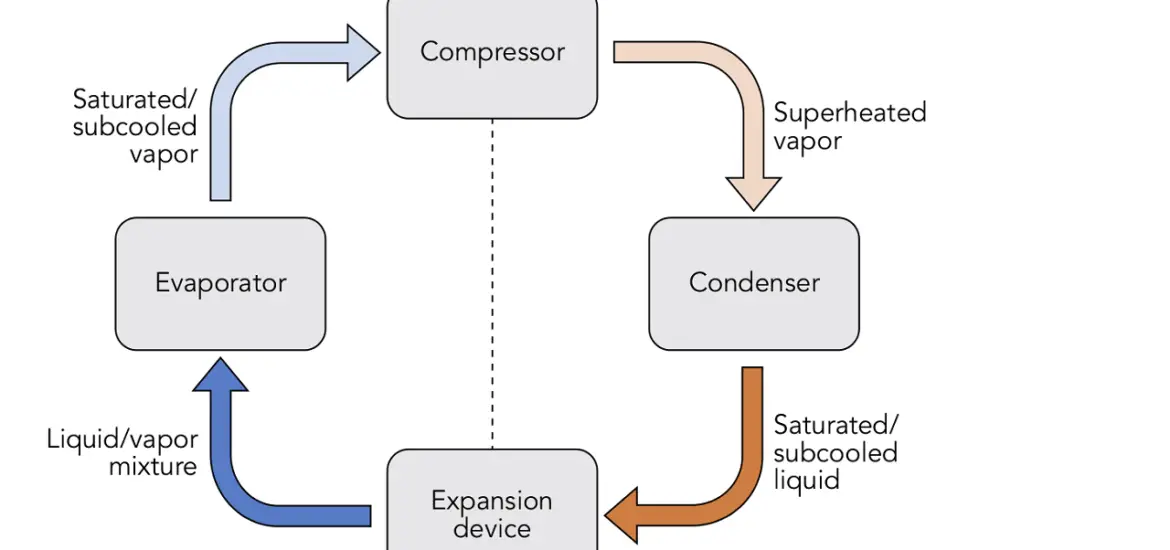
Table of Contents
Definition and Overview
At its core, the vapor compression refrigeration cycle is a method used to remove heat from a space, like your fridge or air conditioner. It’s the backbone of modern refrigeration and AC systems. You might be thinking, “Why should I care about this?” Well, understanding the basics can help you troubleshoot and maintain your appliances, which could save you money in the long run.
Importance of TS and PV Diagrams
Temperature-entropy (TS) and pressure-volume (PV) diagrams are crucial tools in understanding and optimizing refrigeration systems. They’re like treasure maps that engineers use to make your fridge more efficient. Trust us, you’ll want to know how they work.
Vapor Compression Refrigeration Cycle TS Diagram
Components of TS Diagram
The TS diagram has two axes: temperature (T) and entropy (S). It represents various states in the cycle, helping you understand how your fridge works like a charm. Think of it as a snapshot of your fridge’s performance.
Detailed TS Diagram for Vapor Compression Cycle
Compression Process (State 1 to State 2)
On the TS diagram, the compression process is where temperature and entropy change. It’s like squeezing a sponge: the more you compress it, the more water comes out. In this case, heat is removed from the system.
Condensation Process (State 2 to State 3)
Next up, condensation. In this phase, the temperature and entropy change again, but this time, the refrigerant turns from vapor to liquid. It’s like when you take a cold can of soda out of the fridge and watch it “sweat.”
Expansion Process (State 3 to State 4)
As the refrigerant expands, the temperature and entropy change once more. It’s like letting go of a stretched rubber band – it snaps back to its original size and shape, releasing energy in the process.
Evaporation Process (State 4 to State 1)
Finally, we have evaporation. In this phase, the refrigerant turns back into vapor, and the temperature and entropy change again. It’s like boiling water on the stove – as the heat increases, the water turns into steam.
Analyzing TS Diagram for Performance Metrics
By studying the TS diagram, you can identify inefficiencies in your fridge and better understand its performance. Who knew a simple diagram could be so powerful?
Read our other vapor refrigeration articles – Vapor Refrigeration: Easy Guide to Keeping Things Chill
Vapor Compression Refrigeration Cycle PV Diagram
Components of PV Diagram
Similar to the TS diagram, the PV diagram has two axes: pressure (P) and volume (V). It also represents various states in the cycle and helps you understand the inner workings of your refrigeration system. It’s like another angle to view your fridge’s performance.
Detailed PV Diagram for Vapor Compression Cycle
Compression Process (State 1 to State 2)
On the PV diagram, the compression process shows changes in pressure and volume. Remember our sponge analogy? This is another way to see how squeezing the sponge affects its properties.
Condensation Process (State 2 to State 3)
During condensation, the pressure and volume change as the refrigerant turns from vapor to liquid. Just like the cold soda can sweating, the PV diagram helps visualize this process.
Expansion Process (State 3 to State 4)
The expansion process on the PV diagram shows how pressure and volume change as the refrigerant expands. It’s like watching the rubber band snap back to its original size and shape.
Evaporation Process (State 4 to State 1)
Finally, the evaporation process on the PV diagram represents changes in pressure and volume as the refrigerant turns back into vapor. It’s another way to understand how boiling water turns into steam.
Analyzing PV Diagram for Performance Metrics
Studying the PV diagram can help you identify inefficiencies in your fridge and better understand its performance, just like the TS diagram. The more you know, the more you can optimize your appliances!
Comparison of TS and PV Diagrams
Similarities and Differences
Both TS and PV diagrams show different aspects of your fridge’s performance, but each offers a unique perspective. Sometimes, one diagram may be more helpful than the other, depending on what you’re trying to understand. It’s like comparing apples and oranges – both are fruits, but they have distinct characteristics.
Complementary Nature of TS and PV Diagrams
TS and PV diagrams complement each other, giving you a fuller picture of your refrigeration system’s performance. Using both diagrams together can provide valuable insights that you might not get from just one. It’s like putting together pieces of a puzzle – the more you have, the clearer the image becomes.
Conclusion
In the end, understanding vapor compression refrigeration cycle TS and PV diagrams can help homeowners like you maintain and troubleshoot your appliances, potentially saving you money and headaches. So, the next time you open your fridge, take a moment to appreciate the science behind it. Who knew cooling your drinks could be so fascinating?